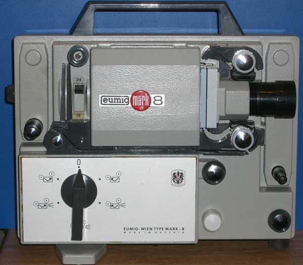
A nicely made machine with some ingenious mechanisms for basically controlling speed, direction, lighting on/off and still frame
The Mark 8 has speed adjustment between 18 and 24fps. The motor is a mains locked synchronous affair and runs all the time, in the same direction and at the same speed.
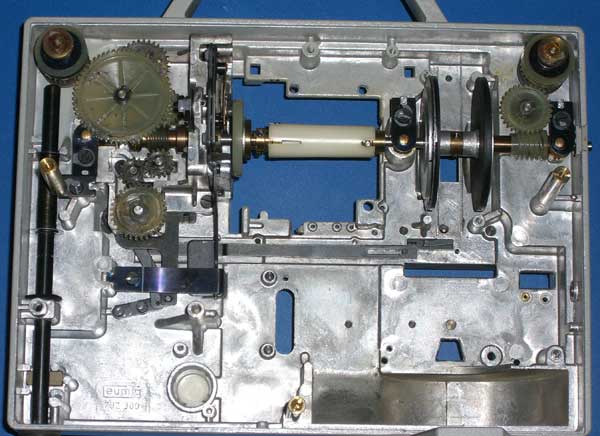
A look at this picture shows how speed and direction control is achieved:
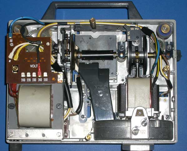
The motor (on the right) is supported at the base on a pivot point which allows the top of the motor to swing from side to side. Its "off" position is in the middle.
There are two large rubber faced discs which effectively contain the motor movement by virtue of the drive disc on the motor shaft pressing against one of the larger discs. If it presses on one disc it will turn the projector mechanism forwards, on the other it will turn it backwards. To change speed, the disc on the motor shaft is moved up and down the shaft. The further down the shaft the nearer to the large disc edge it will be, hence it will run the slowest. The 50/60Hz adjustment moves the band over which the 18 to 24 fps adjustment is made. Interestingly, the transformer does not have steps for 110V, so it is not really dual standard out-of-the-box as far as mains is concerned. An external step-up transformer will overcome the voltage problem and a rotate of the 50/60Hz control will sort the speed.
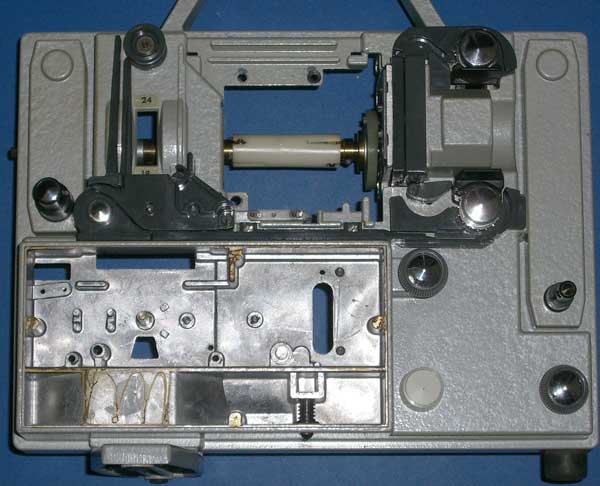
Moving around the the front, here is a shot with the bulb housing, the main control knob and the aluminium faceplate removed.
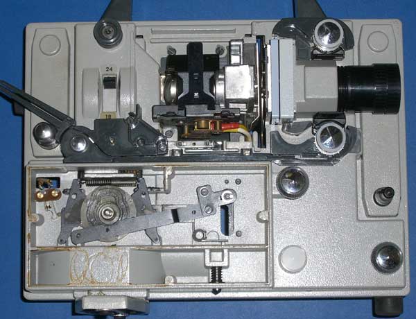
The control switch has six positions. At the top, the motor sits in the middle of the friction discs, so the projector transport is not driven. The motor is kept running to maintain cooling air to the bulb. Top left is reverse with the bulb off, bottom left is reverse with the bulb on. Top right is forward and bulb off, bottom right is forward and bulb on. Bottom is stationary, but with the bulb on. In this mode, a heat filter is brought down between the light source and the film as shown in this picture (spot the difference!).

The conversion
As usual for telecine machines, it is useful to be able to slow down the mechanism. For PAL or NTSC capture using a standard camcorder, 7 or 8 fps is about the maximum we can capture at.
In my case, I'm using a machine vision camera connected via Firewire. Maximum capture speed depends on how much data we can pump down the Firewire cable and with Firewire 400, it is possible to achieve 30fps at 1024x768 pixels. But this is on the limit and will certainly give a top end PC a bit of a workout! My IMI camera will go up to 1388x1040 and the maximum speed at this resolution is 15fps.
Other reasons for being able to slow the projector right down are for making colour captures with a mono camera, HDR captures and scratch and dirt reduction using an additional IR exposure. Each of these requires several exposures per film frame.
Unfortunately, the built in motor runs at a fixed speed and the mechanics only allow a limited speed adjustment range. So, as in my previous two conversions, I decided that a motor swapout is the only solution. I have used the same brushless DC motor from my two previous attempts, hope this will be its last home!
As mentioned above, the whole mechanism on the right hand side (as seen from the back) and that in the control box, is there to just change direction, switch the bulb on/off and keep it cool, and to stop the film burning in still frame mode. In my case, the new motor will be directly controlled for speed and direction. The LED lighting system will need no forced cooling and will not burn the film. This meant I could remove most of that side of the machine's internals, including the bulb mounting mechanism:
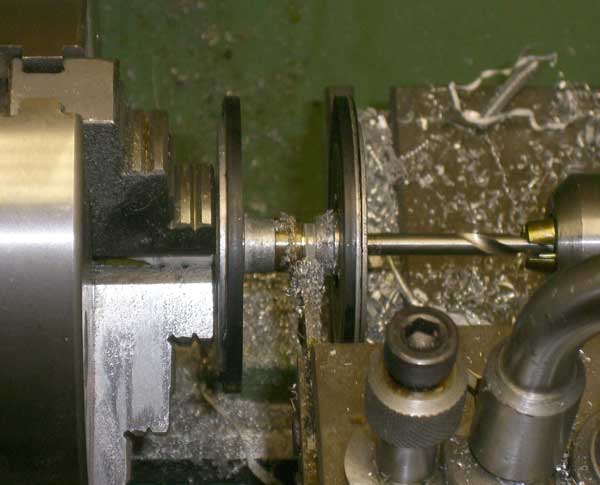
The first real problem was how to get drive from the new motor to the main horizontal mechanism shaft. I couldn't find a way of emulating the friction drive, so went with a pulley arrangement. I replaced one of the friction wheels with a pulley. This was easily done by removing the double friction wheel assembly from its shaft and cutting off the the left hand wheel (as seen from the back), leaving the boss, right hand wheel and the drive into the worm gear intact. The wheel being cut off is on the right in this picture:
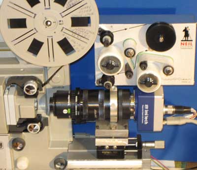
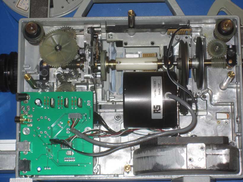
Here is the completed motor installation and LED driver plus motor control board. While adding the pulley, I included a small magnet for the SS443A Hall Effect sensor, the later can be see dangling down from the small circuit board above the pulley:
My latest acquisition is a Film-O-Clean from Neil Research Laboratories. Not installed it yet, but here is a picture of it sitting on the camera, roughly where it will end up: